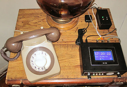
Here is the TIM2015, the GPS (rear right center), slave clock driver (rear far right), and a BT 8746G which serves as a monitor.
The TIM 2015 is a self contained time of day announcement device that measures 5" x 2" x 7" (130 x 50 x 175mm). It answers a telephone line with the current time just as the telephone company's machines used to do. It has voices from the United Kingdom, United States, and Australia, with more on the way.
The TIM2015 is available from Andy Emmerson fully assembled and as a do-it-yourself kit. The device is featured in the Spring 2019 THG (Telecommunications Heritage Group) Journal 106.
Here is the TIM2015, the GPS (rear right center), slave clock driver (rear far right), and a BT 8746G which serves as a monitor.
I purchased the bare-bones kit (case, pc board, and several modules) which Andy referred to as a "box of bits". His documentation is excellent and, for anyone with electronic skills, it is relatively easy to assemble ... once the parts arrive from the UK, US, China, and Korea. Warning: This is no Heathkit®! When ordering parts, it takes a week or less for the goods to arrive from the UK or US; and typically 3 weeks from China or Korea. One item ordered from China took exactly 7 weeks.
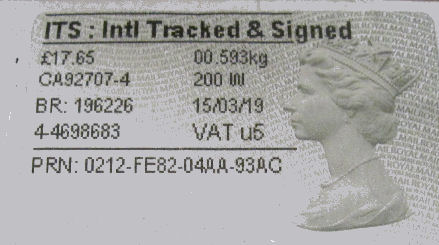
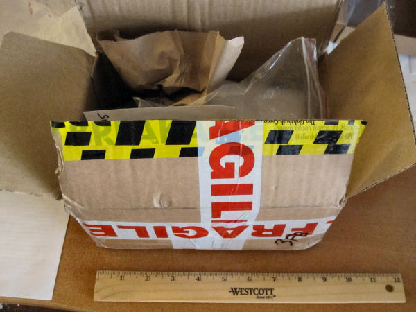
Royal Mail - It took under 5 days to ship the 9" x 6¼" x 4½" "box of bits"
from England to California - 5,500 miles.
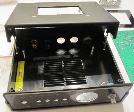
The case - top, bottom, front and rear panels as prepared by Andy Emmerson.
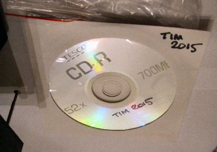
The CD containing the documentation.
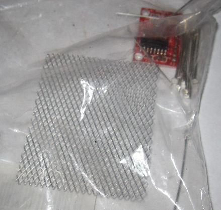
Speaker grill and PAM8403 amplifier module.
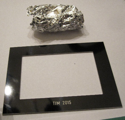
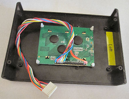
LCD frame. The Adrino and Mitel modem are in the aluminum foil.
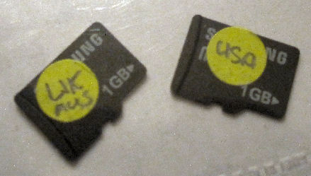
Micro SD cards containing the voice files.
Voices supplied with the kit are:
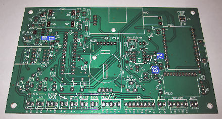
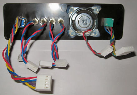
Top of pc board
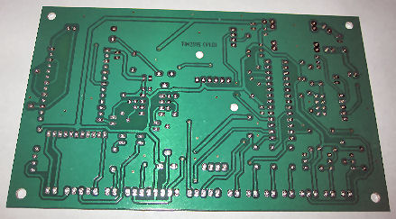
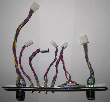
Bottom of pc board
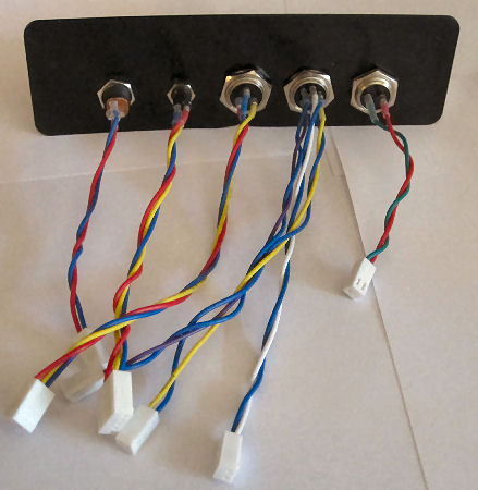
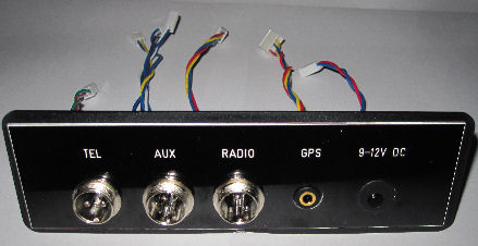
Rear panel
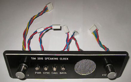
Front panel
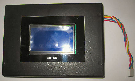
LCD1 - QC12864B2 blue 128x64 Graphic LCD
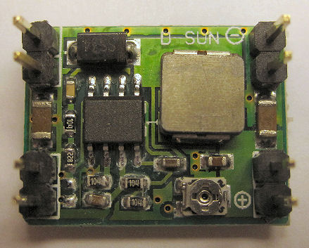
MOD1 - D-Sun Switching Voltage Regulator Module
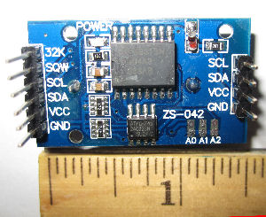
MOD3 - DS3231 RTC Module Clock Time Memory Board
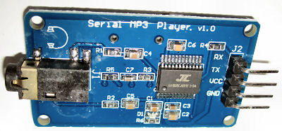
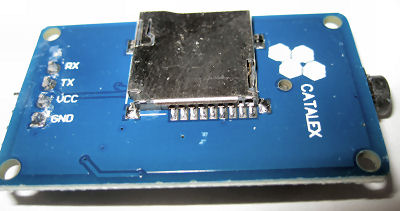
MOD4 - YX5300 Audio Player Module
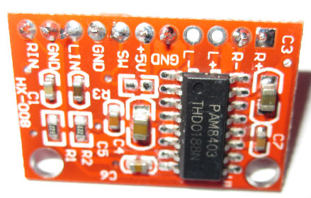
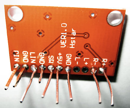
MOD6 - PAM8403 3W Amplifier Module
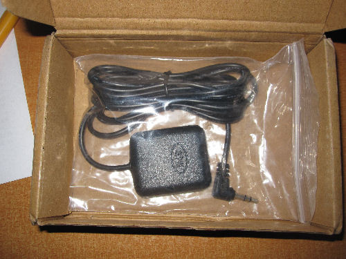
GPS
The unit's time can be synchronized with an external radio (0.1 second accuracy: MSF-- United Kingdom, DCF77-- Germany, WWVB-- United States), GPS (1 second accuracy), or internal Wi-Fi (⅓ - 1 second accuracy: Espressif Systems ESP8266-01). I am using a GPS receiver.
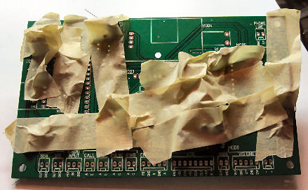
PC board - components mounted and masking taped into position for soldering.
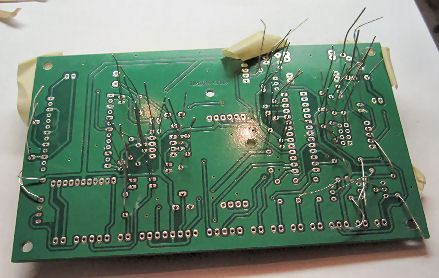
PC board - underside of board before soldering
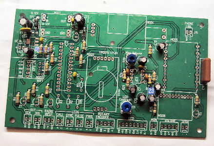
PC board - component side after soldering. Work continued until most "passive"
components (sockets, connectors, resistors, capacitors, and diodes) were installed.
After the "passive" components were installed, the wiring was tested for
continuity, open circuits, shorts to adjacent pins, etc. Then, the 3.3v regulator
and transistors were soldered and tested. The LED resistors will not be installed
until later since they will have to be chosen for consistent brightness.
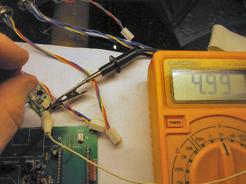
Adjusting the 5v supply
The 5v supply was installed, power was applied, and the 5v supply to each module/socket
was verified. The 3W Amp module was installed. The speaker and headphone/monitor
outputs were testing using a signal generator (set to 33Hz) in place of the
sound card. Then, the modules and chips were installed with the exception of the sound
card (which had not arrived) and modem. The lights lit as they should. The hard reset
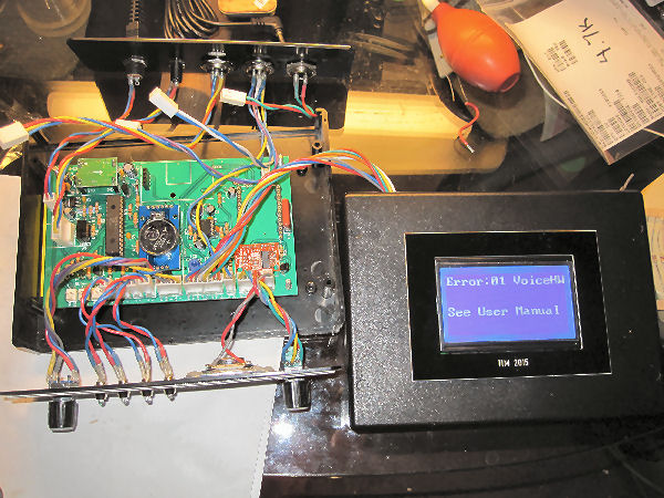
worked - indicating the encoder et al are ok. After adjusting the contrast trim pot,
the expected message "Error: 01 VoiceHW" appeared indicating the display
works properly.
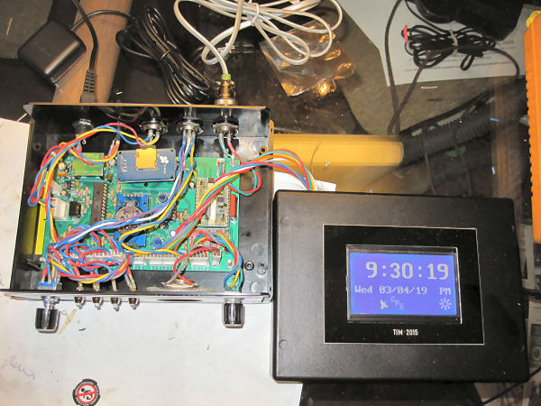
The audio card arrived and was installed along with the modem. Shortly after, the TIM2015
spoke for the first time. In a few minutes, the time synchronized itself from the GPS.
The telephone auto-answer was tested-- my line is connected to a VOIP Magicjack.
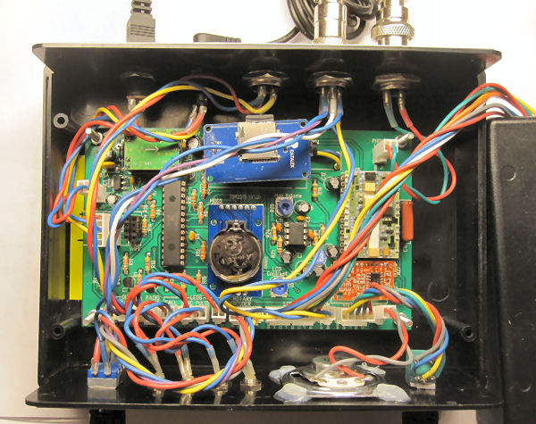
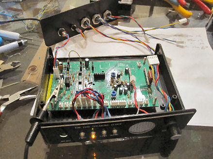
20/20 Hindsight. As the components were placed in the case, as shown above, I realized
that it was not a good idea to use 22 guage stranded-wire and plenty of slack.
Thinner wire with shorter leads would have been better. The wiring had to be neatly
tucked-in before the case was closed.
WWVB is a time service run by the United States Government NIST. The radio
transmitter is in Fort Collins, Colorado-- about 850 miles away from this TIM2015.
The modulation scheme is based on amplitude modulation (AM) and pulse-width modulation (PWM).
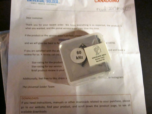
I purchased a CANADUINO Time Signal AM Receiver Kit (SMD) 60KHz, SKU 26019/26020.
Here is the plastic shipping container that I received in the mail.

Contents as received.
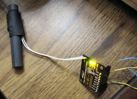
The WWVB prototype. The module board is 28mm long and 21mm wide.
The antenna is 60mm long and 10 to 15mm wide.
There are 4 LEDs on the CANADUINO Receiver.
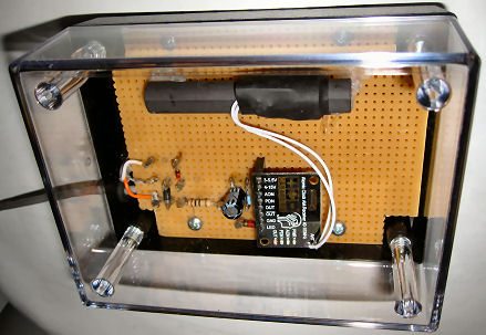
The WWVB receiver in its case. The case was purchased from JK Electronics in
Westminster California and is 4 1/4 inches long, 3 1/8 inches wide, and 2 inches deep.
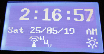
TIM2015 with the Time Source set to WWVB.
The WWVB receiver takes 5 minutes or so to sync during the night. In daylight, it takes hours to sync. Antenna positioning is critical- it must be pointing orthogonally (horizontally and at a right angle) due Fort Collins. The CANADUINO red output LED flashes short-long when reception is good and flickers irregularly when reception is poor. The receiver is susceptible to RF noise and had to be positioned 4 feet away from other electronics. Reception is better in overcast or inclement weather. The blue LED on the TIM2015 follows the red CANADUINO output signal when the bits are understood. In WWV mode, the TIM2015 blue LED flashes continuously 24/7 which is distracting.
The quality of the WWVB signal can be observed on the TIM2015 screen. The waves above the antenna base progress at a rate of one per second growing from 0 to 3 waves. After a minute, the entire antenna image changes to a clock face to indicate success. When reception is poor, the progress bars seldom reach 3 waves.
And for a problem-- 3 times since I started using WWVB, the time was set incorrectly. The error has always been in the seconds-- one time it went 37 seconds slow. I cycled the TIM2015 power and the next time the TIM2015 sync'd, the error was corrected. This only happens during the day. I noticed that the WWVB signal has no checksum and wonder if this problem was due to bad reception. This has never happened with the GPS.
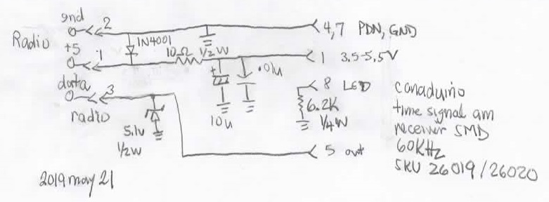
WWVB TIM2015 Interface Schematic.
WWVB has an Phase Modulation (PM) format which uses a different protocol and a hamming checksum. I found one interface module which is both expensive and requires a different electrical connection.
The TIM2015 has a "30S Pulse" output for interfacing to slave clocks. I had never experimented with slave clocks and this piqued my interest.
I purchased 2 slave clocks from eBay. These clocks are the same model as the clocks in my Jr. High School - nearly every clock in that building had a different wrong time - I spent a lot of time staring at the clock and recognized these immediately. A grand old master pendulum clock in the office made the clocks tick each minute. The school's clocks were painted light blue but mine are light yellow.
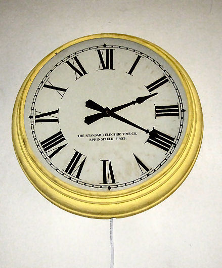
Standard Election Time Company Slave Clock
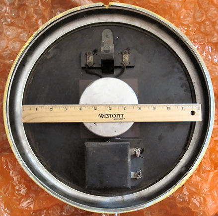
The Standard Electric Time Company clock rear view
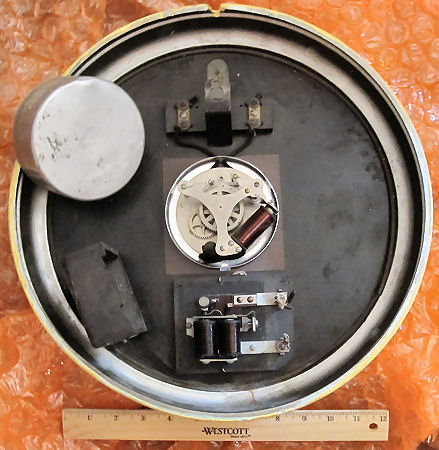
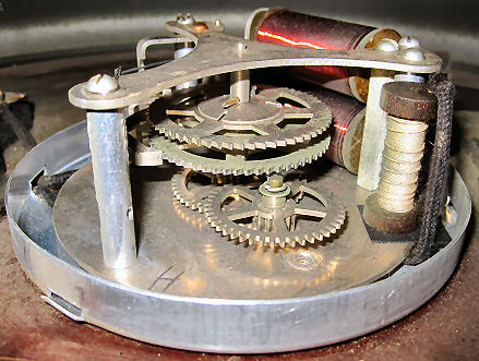
The Standard Electric Time Company clock rear view with dust covers removed showing the clock mechanism and buzzer.
The Standard Electric Time Company clocks were built with 24v 1250 ohm, 12v 320-500 ohm, or 10 ohm 180-200mA ratchet coils. My clocks are of the 10 ohm variety and are designed to be connected in series. The wiring is 1920-1930 vintage and the room wiring on these clocks was cut when the clock was decommissioned - the stubs remain. One clock had one stranded and one solid wire stub both about 18 gauge -- interesting forensics. The insulation crumbles when touched.

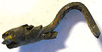
The Standard Electric Time Company clock ratchet pawl.
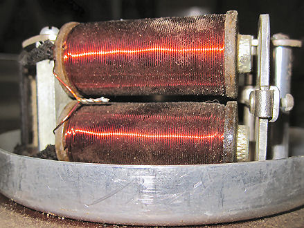
The Standard Electric Time Company clock ratchet electromagnet coils.
The Standard Electric Time Company clock has a shunt resistor wired in parallel with the electromagnets to absorb the voltage spike.
Solid wire stub found on one clock terminal.

Stranded wire stub found on the other clock terminal.
The 12 inch face glass was missing on one clock and cracked on another. The face glass and clock mechanism are held in place by circular springs and there is no cushioning between the glass and the metal bezel. The old face glass had some light green paint covered by light yellow paint hence, the clocks were painted multiple times after assembly. I purchased new glass from Murray's Hardware in Santa Ana, California. They made perfect replicas in less than a day.
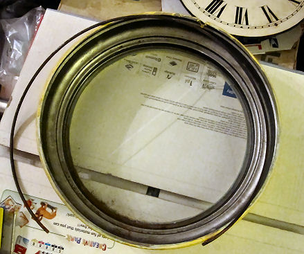
Replacing the face glass.
Empirically, I discovered that the clocks run well at 135mA with a 1/3 second pulse constant-polarity. Polarity is not important. I do not have official specifications. At 300mA, the ratchet is quite loud and the clocks randomly lose 0-3 minutes per day. The sensitivity of the ratchet to current, the series wiring, no synchronization mechanism, and the lack of maintenance as a whole at the school may explain why the school clocks were off.
The TIM2015 by design creates 30 second pulses however these slave clocks require 60 second pulses. My driver circuit uses a 4027 JK flip flop (30s to 60s) followed by a 4098 non-retriggerable one-shot (pulse width) followed by a IRL540 MOSFET (clock coil driver). The driver has an on/off switch and a pushbutton to manually step the clocks. The 2 clocks are connected in series with a 24v DC wall wart, a 250mA fuse, and a 150 ohm 5w resistor. What we have here is a 90-100 year old clock controlled by a TIM2015 and an MOSFET! I added the one-shot to reduce the chance of a cable or other problem from applying constant DC to the clock coils.
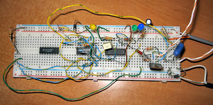
Prototype electronics.
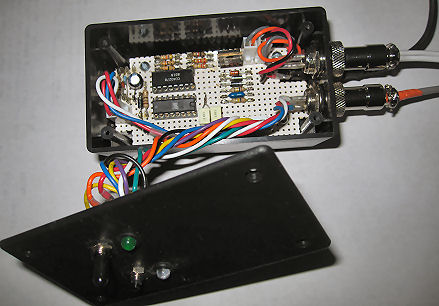
Final electronics.
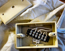
Distribution box connecting the driver to the clocks. The 150 ohm current limiting resistor can be seen.